Innovation and process optimization driving success
Number 1 container port in New Zealand
The Ports of Auckland (POAL) operates New Zealand’s largest container port. The terminal is situated in the heart of Auckland and has the largest consumer market in the country on its doorstep. More than 1.4 million people (out of New Zealand’s 4.5 million population) live in Auckland. While this ensures that the port is dominant in imports (full imports are 37% of total volume) full exports still make up 19% of its volume.
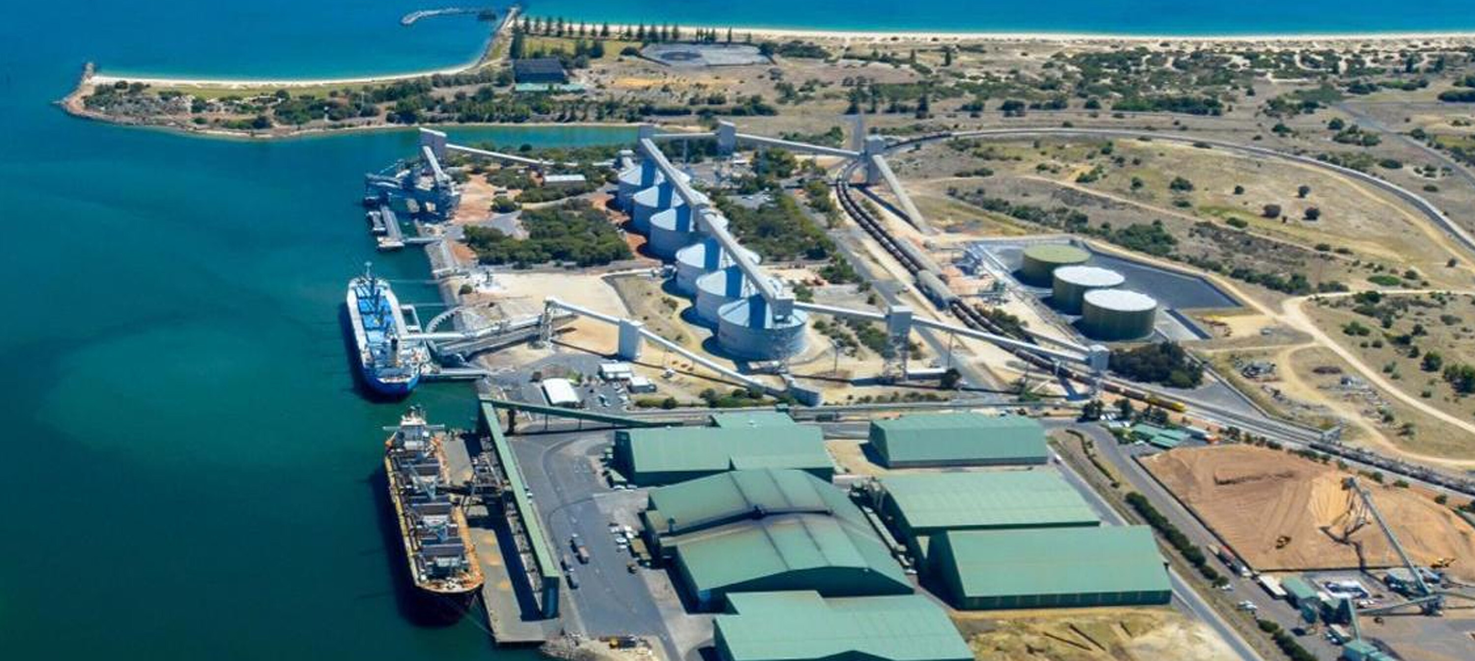
The container terminal is operated on the Fergusson berth (see Figure 1), and handles just under 1 million TEU annually. On a small footprint, operated with 1 over 2 straddle carriers, with the flow being predominantly import-export, this is an everyday puzzle to achieve quality of service both waterside and landside.

Figure 1: Overview of the Ports of Auckland
Preparing for the future
In order to be prepared for the future, POAL partnered with TBA in 2008 to develop a long term plan, and to keep this up-to-date as time progresses. Since then, POAL and TBA have been working together on the ‘master planning’, as well as enhancing operational efficiency to make it not only the largest but also the most productive and efficient terminal in New Zealand.
Current results speak for themselves: despite the large volume growth over the last couple of years, the waterside productivity has kept increasing to achieve current (net) crane rates above 32-35 containers per hour, and good truck turn times. One of the concerns though is the yard occupancy, despite a relatively low dwell time.
The yard capacity problem is one of the main focus areas for the master planning exercise. As the port cannot really expand – there are some additions to the current footprint, but in the overall picture, this is quite limited – the solutions have to be sought in different directions. A first obvious step is to implement 1 over 3 straddle carriers, as it would immediately increase capacity by at least 30%. Before jumping to conclusions, several solutions where thoroughly researched – various perpendicular, and parallel RMG solutions have been compared by means of simulation (see Figure 3).
One of the drawbacks of any solution with RMG’s is the odd shape of the facility. RMG’s lend themselves quite well to rectangular sites, and the terminal at hand is anything but that. Moreover, the North berth (the berth on the left in Figure 3) – currently under development – makes operation from the end-serving ARMG’s – far from optimal. Also parallel solutions with cantilever RMG’s (see Figure 3) were discarded as the integration with straddle operation is inherently complex due to the need to avoid mixing of road trucks and straddle as well as the interaction between CRMG’s and straddles.

Figure 2: Screenshots from the decoupled mode of operation (yellow straddle being manual, blue straddles being 1 over 3 automated)
Decoupled semi-automated straddle operations
So, after considering various options for the yard expansion, the decision was made to look at using automated 1 over 3 straddles to intensify the operation. The port is currently consulting with staff over the proposal and has commissioned a scoping study to examine the proposal in more detail. The proposal is for semi-automation, where the yard operation and truck operation would be automated, and the service to the ship would still be manual. In between, there would be a decoupled buffer where automated straddle carriers and manual interchange containers would operate in a similar fashion to end serving ARMG’s and straddle carriers. This buffer would be 4 TEU long, and every straddle row would have its own interchange buffer. Furthermore, the yard would be 1 over 3, with automated machines, where the waterside would continue with 1 over 2 (manual) machines.
This plan comes with a number of advantages:
- The conversion to 1 over 3 straddle carriers is seamless, as there are no civil works to be performed.
- The perceived safety risk of 1 over 3 operation can be avoided by only going 1 over 3 with automated machines which automatically adjust speed in case of risk of tipping.
- Automation of the waterside operation is the most difficult and carries the risk of a drop in performance. This is avoided.
- Natural staff turn-over and growth of the business would align with the three-year implementation period of automation, and the lesser demand for straddle drivers.
- The existing fleet of 1 over 2 machines can still be used until they are life-expired.
- The area where most damage to containers and machines is incurred is the yard, hence a maximum reduction of wear, tear and damage is expected.
- The test phase can be performed in a small confined area, only containing a few yard rows and 1 truck interchange zone, hence minimizing the capacity impact of the test phase.

Figure 3: Initial plan for the Fergusson terminal with perpendicular ARMG's (left picture), and sketch with parallel CRMG layout (right picture)
Optimizing a novel mode of operation
The decoupled straddle model – as we call it – is a novelty. Although there are several terminals world- wide that have straddle carriers in the yard, and terminal trucks on the quay – e.g. Northport in Malaysia – an automated straddle / manual straddle operation is new. In order to ensure that the productivity targets will only be affected positively when introducing this mode of operation, POAL asked TBA to carry out a series of simulation runs. The level of accuracy of these simulations is such that they are very close to real operations under undisturbed circumstances, as has been proven in recent performance testing at Maasvlakte 2. The simulations were focused on the optimal yard layout, from a handling and traffic point of view: a key part in straddle operations. Three options were being considered (see Figure 4). The options were developed because of the berth expansion project, providing the terminal with a high performance berth, with deep draught, and tandem-lift STS cranes. In order to facilitate this berth, the buffer (indicated in yellow in Figure 4, and shown in the middle layout) should face the berth, as a buffer (and yard) facing the existing berth (left layout in Figure 4) would make the distance to serve the North berth (berth on the right side) long. Besides the traffic around the North-West corner would become very dense, as our traffic analysis showed.

Figure 4: Three yard layout options for decoupled automated straddle operation
One option that was taken into consideration is the one shown in the right picture, with a buffer facing the North berth, and the yard facing the existing Fergusson berth. The automated straddles would then drive in the middle alley to the buffer on the right side, where the hand-over to the manual machines would take place.
Based on the simulation results it was decided to implement the layout with a split yard (the middle picture), as it provides the best overall performance, and especially to the new high performance berth. From the simulation, we saw net productivities of 42 containers per hour across all STS cranes, during peak operations, and 45 containers per hour for the new tandem cranes. This in combination with twin- lift and tandem (twin 40’) lift operation, and 3-4 straddles per STS crane (depending on the mode).
Outlook
So, from where the port is now, to a fully expanded terminal, with a whole new high performance berth, there is still a way to go. A way that increases the terminal’s throughput capability from 1.3M TEU today to 2.1M TEU at full build-out, and having the capability of handling 2 large (330m) vessels at the same time at berth productivities exceeding 150 containers per hour.
For the Port of Auckland, this is a solid future outlook, staying within the boundaries, reducing the proportional need for land, and still serving the ever growing New Zealand export market while catering for the local demand for import. As a potential bonus, in the light of ever growing ships, and the cascading effects even down-under, the port could serve as a transshipment hub for New Zealand, where most transportation is done by sea due to the low density of the population. As such, fewer ports would need to invest in deepwater berths, higher and broader cranes, as well as the negatives of increased peaks in the yard.
This article has been written by Dr Yvo A. Saanen, Managing Director TBA Delft, and Tony Gibson, Managing Director Ports of Auckland in New Zealand and was published in Port Technology Magazine in December 2015.
Share this
You May Also Like
These Related Stories

Mega ships: virtue or terminals’ worst nightmare?

New Director appointed to TBA’s Control Automation team
